Flip Dot AND Gate
Attempt to make an AND gate using magnetic hematite beads.
Material List:
30 AWG Enameled copper wire
10 mm Hematite magnetic beads
12 mm Dowel or Sharpie marker
Conductive thread
Snap buttons
Metal spring (optional)
Paracord
Painter’s tape
Felt
Due to issues highlighted in the tutorial (at the end of the page), I had to limit the travel of the flip dots. To do so I cut up the metal spring of a pen. Unfortunately, after this modification was done, I had tremendous difficulties making the dots flip.
What is a logic gate?
A logic gate is a device (either virtual or mechanical) used to execute a Boolean function. Logic gates are the bedrock of modern computing.
Logic gates can be divided into two categories:
One input logic gates
Two input logic gates
The One input logic gates are:
Buffer
Inverter
The Two input logic gates are:
AND
NAND
OR
NOR
XOR
XNOR
The AND gate is a basic gate that implements a logical conjunction (^) and it behaves according to the Truth Table above.
An output value of 1 is only possible if both inputs have a value of 1 as well.
Making a mechanical AND Gate:
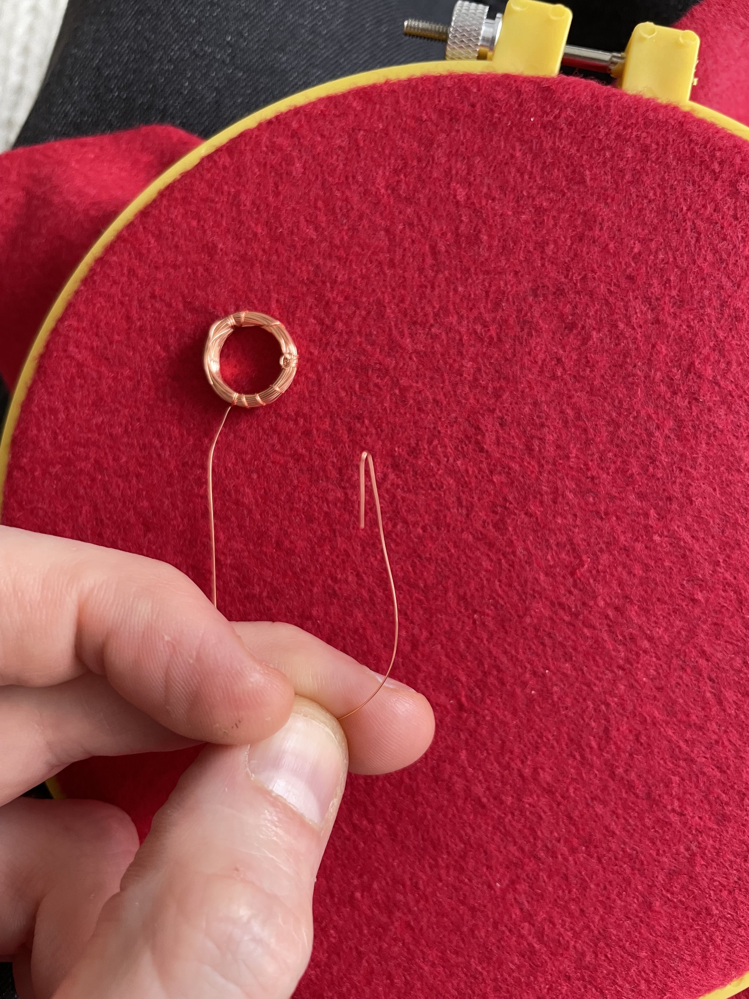
To start, I began by making 3 copper coils using 30 AWG enameled copper wire using a Sharpie marker to help me wound them (more info in the tutorial below).
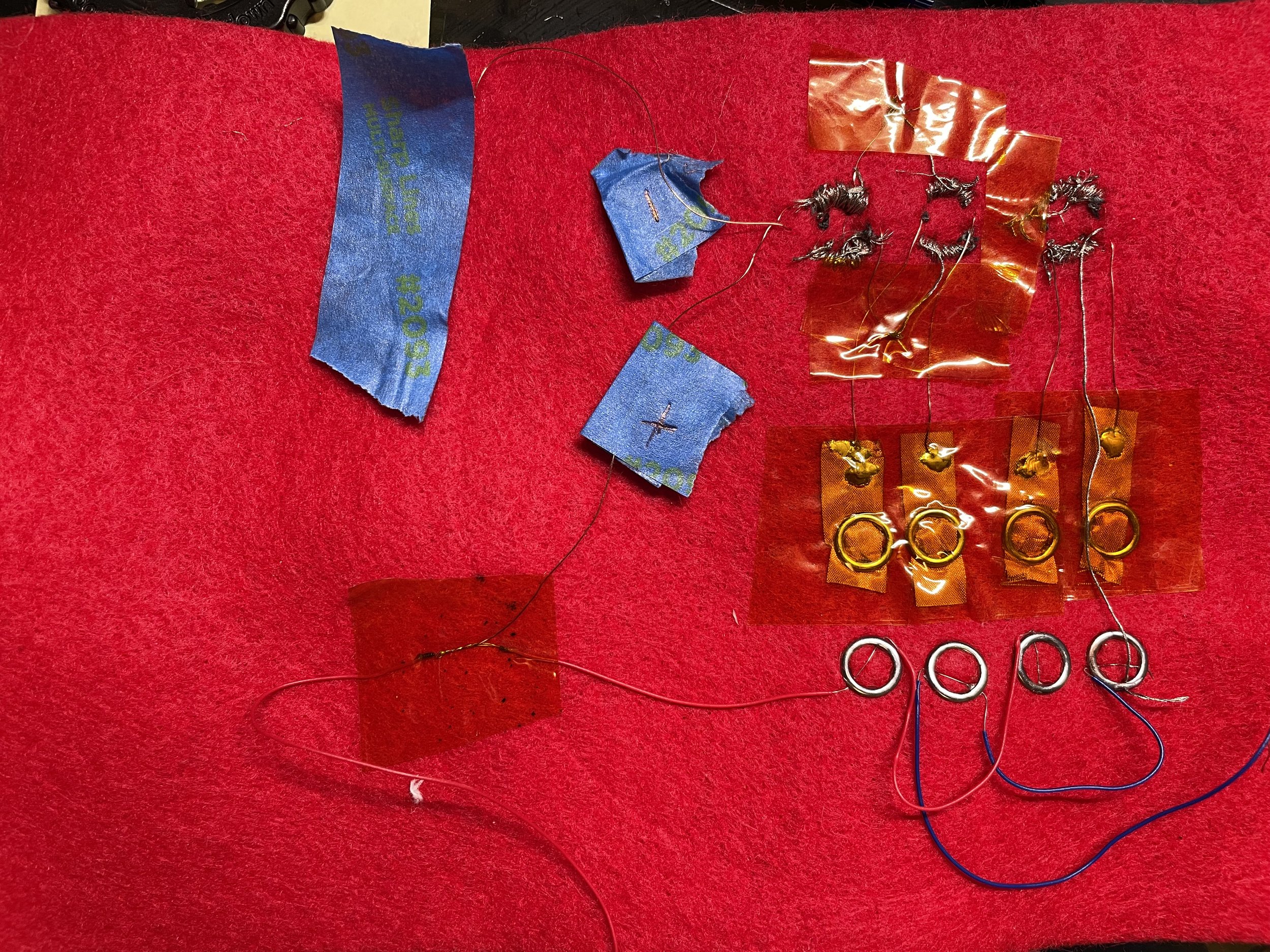
I subsequently embroidered the coils onto a piece of red felt using conductive steel thread.
The ugly mess that is the back of my defunct AND gate.
Example of how the AND gate should work: input A (left most bead) is set in the 0 position while input B (center bead) is set in the 1 position. As per the Truth Table above the output remained at 0.


